
What Is the Strangler Fig Pattern?
The strangler fig pattern is an approach to legacy system modernisation in which a new system is built incrementally alongside the existing one. Functionality is transferred component by component, with the legacy system continuing to operate throughout, until it has been fully replaced and can be decommissioned.
What Is the Strangler Fig Pattern?
The concept was coined by Martin Fowler in 2004, who observed strangler figs in the rainforests of Queensland and recognised the analogy with software modernisation. The core insight was that you do not need to stop a system to replace it, since you can build around it while it continues to run.
In practice, the strangler pattern works through a proxy or routing layer that sits between users and the underlying systems. Initially, all traffic flows through the legacy system as before. Then, as new components are built and validated, traffic is redirected to them — first partially, then fully. The legacy system handles less and less over time until it is idle and can be switched off.
Four principles define the approach: the business never stops during modernisation; the system is replaced in components rather than all at once; both old and new run in parallel during each transition; and every step can be reversed if something goes wrong.
Why It Is Safer Than a Full Rewrite
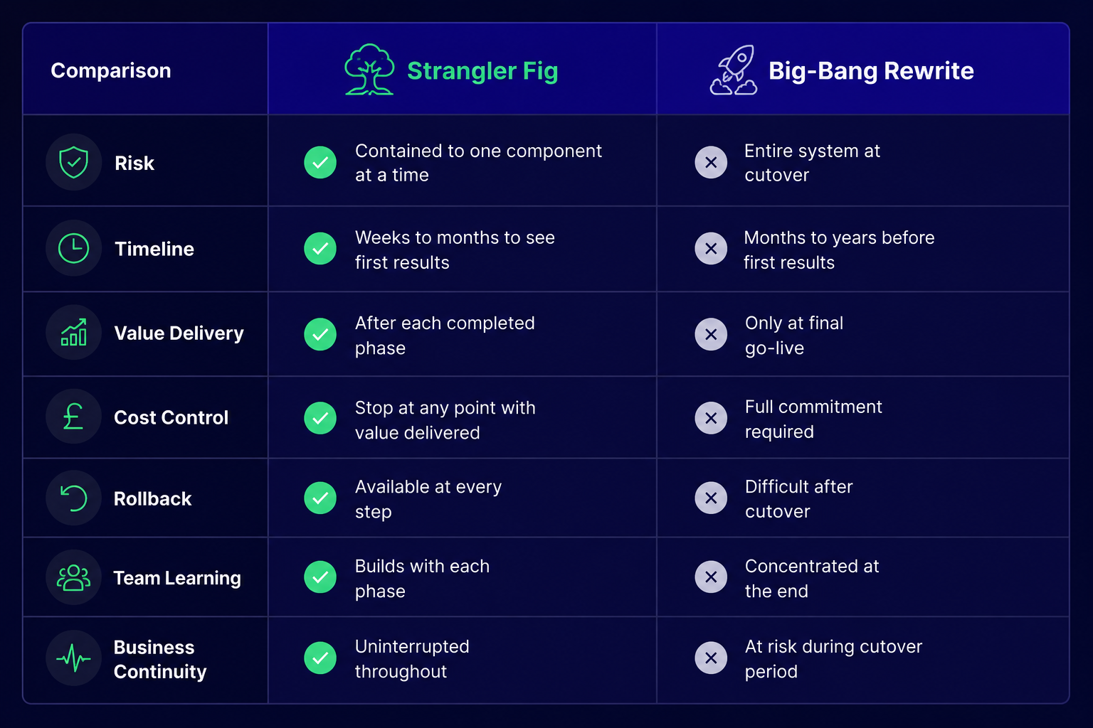
A complete rewrite asks the company to wait because it takes months to develop, followed by a single cutover point where everything changes at once. If the new system has problems, which new systems always have, the business is faced with limited options. You can roll back, reverting to a system that may have drifted out of sync during the development period, or you can continue forward, meaning operating on an unstable system.
The strangler pattern changes the risk profile at every stage. ThoughtWorks, which has applied the pattern across large-scale modernisation programmes, describes it as a viable alternative to the big bang approach precisely because it is iterative: each cycle of building, rerouting, and retiring a component is self-contained and reversible. According to the Microsoft Azure Architecture Center, it is a well-established pattern for incremental legacy migration. It shows the facade layer that handles requests between the old and new systems during the transition, ensuring that users are not inconvenienced during the process.
How the Strangler Fig Pattern Works: 4 Phases
Phase 1: Identify and Map
Before any development begins, the existing system needs to be understood as a set of components rather than a single block. What are the distinct functional areas? What depends on what? Which components are causing the most operational pain, blocking new features, or creating the most risk?
The output of this phase is a component map with a prioritised order for migration. The starting point should be the component that is most painful to the business, not the most technically challenging. Early wins build confidence and demonstrate value to stakeholders.
For a UK manufacturing company running a 15-year-old .NET order management system, this mapping exercise might reveal six functional modules: orders, inventory, billing, reporting, customer records, and dispatch. This is the logical starting point if billing is causing daily operational problems, such as failed integrations with the payment provider, staff hours spent on manual reconciliation, or other issues.
Phase 2: Build the New Component
With the target component identified, a new version is built on a modern platform alongside the legacy system. This new component does not replace the legacy system during this phase; instead, it coexists with it. A routing layer is responsible for directing traffic between the old and new components. The new component reads data from the legacy database, processes it using modern logic, and writes the results back. The legacy system continues to operate as before.
This is also the phase where the strangler pattern is most commonly applied to a monolith-to-microservices migration. Decomposing a tightly coupled monolith involves extracting each service individually. The routing layer routes traffic to the proper destination, and each new microservice manages a particular domain that was previously housed within the monolith. The monolith shrinks gradually rather than being rebuilt all at once.
Phase 3: Redirect and Verify
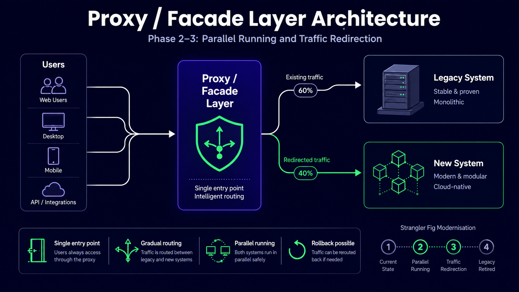
Once the new component has been built and tested internally, traffic is slowly redirected to it. A sensible starting point is new customers or new transactions: this involves lower risk because no historical data is at stake. Once that cohort is stable, the migration expands: 25% of existing users, then 50%, then all.
At each stage, the results from the new component are compared against what the legacy system would have produced. Any discrepancy is investigated before the migration proceeds. During this parallel running period, the legacy system's hidden business logic, such as edge cases, rounding rules, and exception handling, that has been operating covertly for years eventually comes to light.
At this phase, a rollback plan is a must. The business requires not a theoretical one, but a tested, documented procedure that the team can execute in minutes if something goes wrong.
Phase 4: Decommission the Old
Once the new component handles 100% of traffic with stable results, the legacy module is decommissioned. The routing layer is simplified. The team goes on to the next item on the priority list after archiving the legacy code, which is kept accessible as a reference in case someone has questions about its past behaviour.
For the manufacturing company in the example, billing now runs on a modern cloud platform integrated with the payment provider, reducing processing time and eliminating manual reconciliation. The next module on the list is reporting. The full modernisation programme is planned over 18 months across all six components.
How the Pattern Works in Practice: An Illustrative Example
To illustrate how the pattern plays out in practice, consider a UK manufacturing business with 60 staff that had been running the same .NET application for 15 years. It managed orders, inventory, billing, reporting, customer records, and dispatch. The system worked, but it created three specific problems: billing could not integrate with their new payment provider, month-end reporting took four hours to generate, and there was no way to access any of it remotely.
A full rewrite was considered but rejected, since the system was too critical, the business could not afford extended downtime, and the total rewrite cost was difficult to justify as a single capital commitment.
The strangler pattern was applied over four months for the first module. Phase 1 identified billing as the highest-priority target: the clearest integration requirement, the most painful operationally, and relatively well-bounded within the system. Phase 2 built a new billing module on a modern cloud stack and connected it to the new payment provider, while the legacy billing system continued to process all live transactions. Phase 3 ran both modules in parallel for six weeks, starting with new customer invoices and expanding to all billing. Phase 4 decommissioned the legacy billing module once the parallel results were consistent.
After four months, there was no longer any manual reconciliation, billing was integrated with the payment provider, and processing time was greatly decreased. The legacy system was still running for the other five modules, and that was fine. The next phase targeted reporting.
This example is illustrative. Timelines and outcomes vary depending on the system, the team, and the scope of each component. The structure of the approach is consistent.
When to Use the Strangler Fig Pattern (and When Not To)
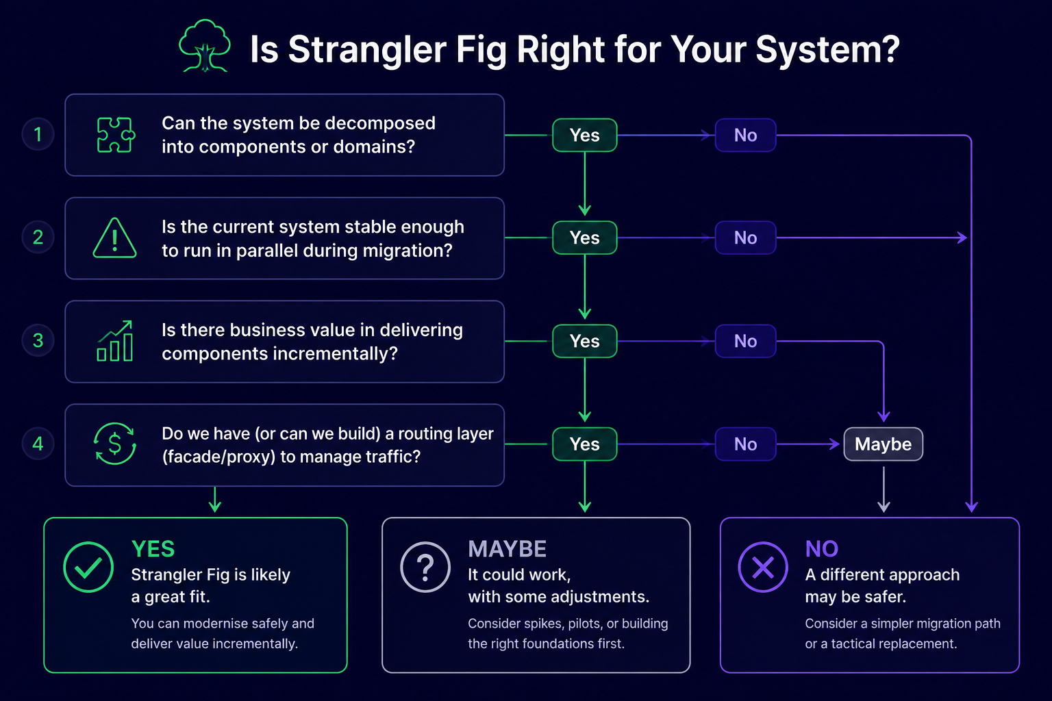
The strangler pattern fits well when:
- The legacy system is operational and delivering value, but it is constraining the business.
- The system can be decomposed into identifiable functional components.
- The business cannot tolerate significant downtime during modernisation.
- Budget is limited, and the team needs to demonstrate value incrementally rather than at the end of a long project.
It is less suited when:
- The system is simple enough that a clean rewrite would take weeks rather than months.
- The system is so tightly coupled that no component boundary can be drawn without restructuring the whole, in which case a preliminary refactoring step is needed before the pattern can be applied.
- The technology is so outdated that building a routing layer between old and new is technically impractical.
The honest position: strangler fig is not the answer for every legacy migration. Some systems are better candidates for a targeted rewrite of a specific module, or for replacement with a commercial off-the-shelf product. What makes the pattern valuable is not that it is universally applicable, but that it applies to a large proportion of the legacy systems that real SMBs are running today.
Common Mistakes When Applying the Strangler Fig Pattern
Starting with the most complex module. The first phase should build team confidence and quickly demonstrate value. Taking off with the most technically complex component risks the whole programme on a difficult first step, so start with the most painful, not the hardest.
Skipping the routing layer. The gradual traffic redirection is achieved through the proxy or facade layer, which serves as a barrier between users and the underlying systems. This layer is not an optional architectural detail. Without it, switching between old and new becomes a binary event rather than a controlled migration.
Letting temporary integrations become permanent. The bridges built between legacy and new systems during the migration are designed to be temporary. If they are not actively decommissioned once the migration is complete, they become permanent technical debt in the new system.
Underestimating data migration. The logic of the strangler pattern is straightforward, while the data migration within each phase is not. Data accumulated over years in a legacy system carries inconsistencies, undocumented transformations, and implicit business rules that only become visible when they break. This is consistently the most time-consuming part of each phase.
No tested rollback procedure. Every phase should have a thoroughly rehearsed rollback plan. The value of the strangler pattern is that any step can be reversed, but only if the team knows how to do it quickly under pressure.
How This Connects to Our Approach
The strangler fig pattern is the foundation of how Hollinford approaches legacy system modernisation. We do not recommend full rewrites as a default, because for most UK SMBs they carry more risk than the situation warrants. We start with an assessment of the existing system, identify the component order that maximises early value and minimises risk, build alongside your current system, and migrate in phases with rollback available at every step.
For a detailed description of how that process works in practice, see how we work.
Key Takeaways
- The strangler fig pattern replaces a legacy system component by component rather than all at once, with the legacy system continuing to operate throughout.
- It is safer than a full rewrite because every step delivers value, every step can be reversed, and the business never stops during the process.
- The four phases: map the existing system and prioritise components; build the new component in parallel; redirect traffic gradually with a tested rollback plan; decommission the legacy component once migration is complete.
- The pattern is not universally applicable: systems that are too simple, too tightly coupled, or too outdated for integration may need a different approach.
- Data migration is consistently the most complex part of each phase and should not be underestimated.